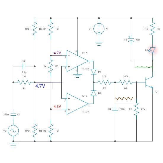

#Clipping detector amplifier plus#
#Clipping detector amplifier install#
Verifies that the gain overlap of an install hasn't been tampered with after install.Checks gain overlap of an audio system without making any adjustments to the existing settings.Sets audio system gain overlap, continuously variable from 0.0dB - 15.0dB in 0.1dB steps.The input circuitry of Type 2718 includes a. What is the difference between this and the original DD-1+? The output current and voltage can also be monitored using two BNC connectors on the back panel. An envelope detector is a circuit that takes a high-frequency amplitude modulated input and produces an output which is the envelope of the AM signal. In practice, quite a lot of clipping can occur before you can hear it. It indicates when the amplifier has reached its limit and is clipping the peaks of the audio signal. It can also be useful for detecting distortion in the audio signal caused by poorly designed or malfunctioning audio equipment. This property can be used to make non-linear amplifier circuits which have either logarithmic or anti-logarithmic (exponential) input to output relationships. A clipping indicator is a useful accessory on any audio amplifier. These are discussed in detail as given below − Positive ClipperĪ positive clipper is a clipper that clips only the positive portion(s) of the input signal.The purpose of this tool is to enable the installer to set the gain of an audio amplifier to match the source unit’s output level, accurately and quickly. The main advantage of clippers is that they eliminate the unwanted noise present in the amplitude of an ac signal.Ĭlippers can be classified into the following two types based on the clipping portion of the input. Clipping may occur, for instance, when an amplifier is overdriven and attempts to deliver an output voltage or current beyond its maximum capability, i.e. Due to this, the peak to peak amplitude of the output of a clipper will be always less than that of the input. Clipping is a form of waveform distortion that limits a signal once it exceeds a certain threshold.

That means, the output of a clipper will be same as that of the input for other than the clipped part. Op-amp based ClippersĪ clipper is an electronic circuit that produces an output by removing a part of the input above or below a reference value. In this chapter, you will learn in detail about clippers. There are two types of wave shaping circuits: Clippers and Clampers. Below is the schematics for a Basic Peak. The diode is placed in forward biased condition and for output, the oscilloscope probe is connected between the diode and capacitor.

In our circuit, we are giving a sine wave input from a 220v to 6v step-down transformer.


 0 kommentar(er)
